Gallery
No video available.

Facing the "volumetric corruption" requirement, this post documents why we ruled out heavy solutions like Uber Shaders and RT-driven approaches, pivoting to a lightweight Native Decal Projector with mathematical static/dynamic decoupling.
When receiving Mike’s requirement for “volumetric corruption with dynamic wind feedback,” the initial instinct was to lean towards complex, cutting-edge techniques. However, during the actual R&D and testing phases, I had to make pragmatic trade-offs between performance and visual fidelity.
This post-mortem not only documents how our final Shader is constructed, but more importantly, why we chose NOT to use those “advanced-sounding” solutions, and how we left the door open for future extensions.
In the early stages of the project, to completely solve the lack of volumetric depth in 2D decals, I evaluated several highly ambitious technical routes:
Route A: Uber Shader Injection Injecting the corruption logic directly into the Master Node of all terrain and prop materials via a Subgraph, utilizing true world-space coordinates for vertex-level influence.
Route B: Mesh Decal Proxy
Spawning a real semi-transparent sphere mesh at the corruption site and calculating soft blending at intersections by reading the CameraDepthTexture.
Route C: Render Texture Channel Packing (Enrico’s Proposal) Discarding global variable parameters in favor of a real-time Render Texture (RT). By packing the corruption shape, wind perturbation, and footprint state into different channels, this would allow for fully independent physical interactions for every corruption ring in the scene.
Theoretically, all these approaches are perfectly valid and represent standard practices for environmental VFX in AAA engines. However, following a rigorous Profiler audit, I decided to put them on hold.
The primary reasons for discarding the above solutions boil down to a poor Performance-to-Visual Ratio and exorbitant maintenance costs.
Transparent render queue, meaning they cannot benefit from Early-Z culling. If multiple corruption spheres overlap in a narrow corridor, the fragment shader (frag) overdraw would instantly blow through our performance budget.Based on these considerations, I decided to pivot to the most lightweight, non-invasive solution available: HDRP Native Decal Projector.
Having committed to Native Decals, the new challenge emerged: Using purely mathematical logic, how do we make a 2D projection feel like an organic fluid torn by the wind, without clipping awkwardly into the environment?
Through a synchronized effort between C# and Shader Graph, we tackled three major pain points:
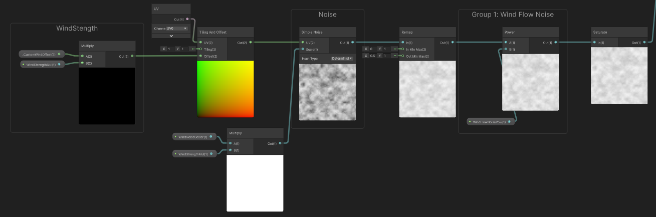
Initially, I multiplied Time * WindSpeed directly inside the Shader to pan the noise. The fatal flaw? Whenever wind speed changed smoothly, the output of Time would jump drastically, causing the VFX to aggressively flicker and snap.
The Solution (C# Phase Accumulation): Strip the Shader of its time-calculation duties. Instead, use Time.deltaTime in the C# script to calculate the incremental physical distance traveled each frame. We pass this stabilized, continuously accumulating vector (_CustomWindOffset) to the Shader, while applying modulo operations to prevent floating-point precision loss over long play sessions.
If we applied the wind offset to the global UVs directly, the entire corruption pit would slide across the floor like a skateboard.
The Solution (Static/Dynamic Decoupling): Strictly isolate the static and dynamic components within the Shader. Static UVs are exclusively used to generate the central black hole mask; meanwhile, the wind perturbation doesn’t shift the UVs but is instead added to the Radius of the Distance node. This locks the pit in place, while allowing only the outer flames to stretch downwind.
When a decal is projected near a tree trunk or steep wall, the 2D planar projection inevitably creates hideous vertical stretching.
The Problem: Severe stretching artifacts caused by Decal projection on vertical surfaces.
We deployed a “Dual Defense Mechanism” to handle this:
Decal Layer Mask. This takes effect at the base Culling stage, serving as a zero-cost hard isolation.The Solution: Vertical stretching is smoothly eliminated after applying the Height Fade Mask.
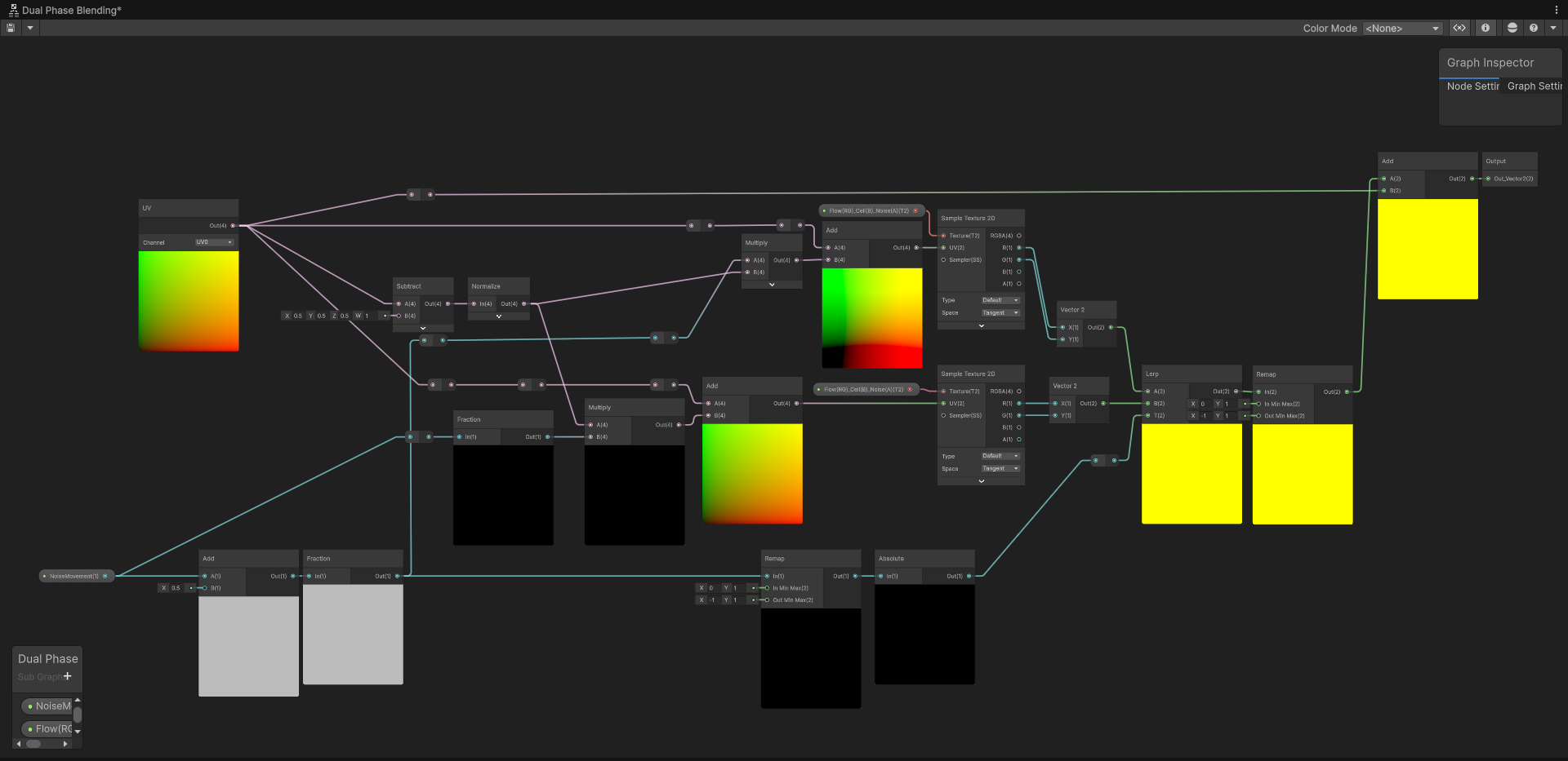
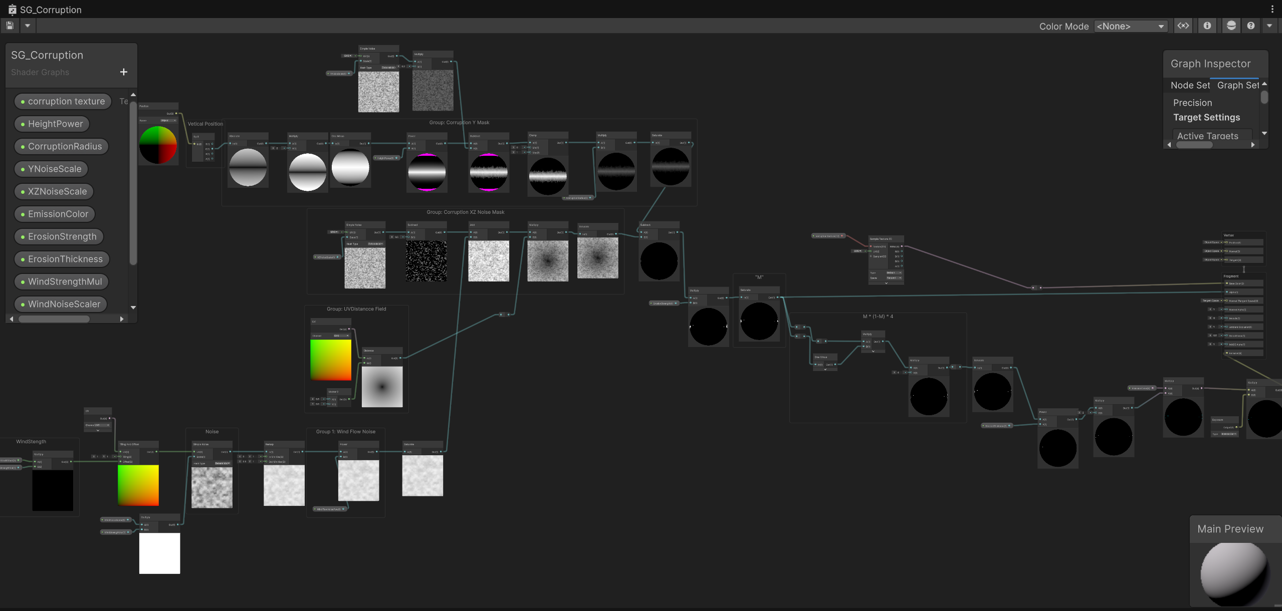
To execute the concepts above, the Shader is cleanly modularized into several functional groups:
Shader Graph Global Overview: Clean functional modularization
Receives the accumulated variable _CustomWindOffset from C#.
This is the anchor for the underlying corruption pit, ensuring the core doesn’t drift.
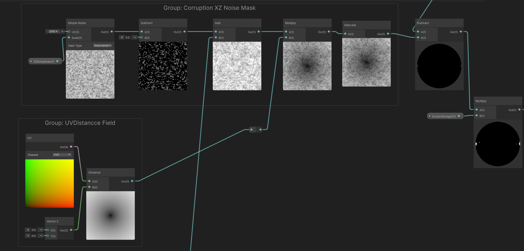
UV coupled with a center point of (0.5, 0.5) fed into a Distance node to calculate a perfectly static radial gradient. Inside this group, introducing any wind variables is strictly prohibited.This is the heart of the deformation and restriction logic. I split it into two dimensions: planar perturbation and height clamping.
Dimension 1: Downwind Surface Stretching (XZ Noise) Handles fluid deformation on the 2D surface.
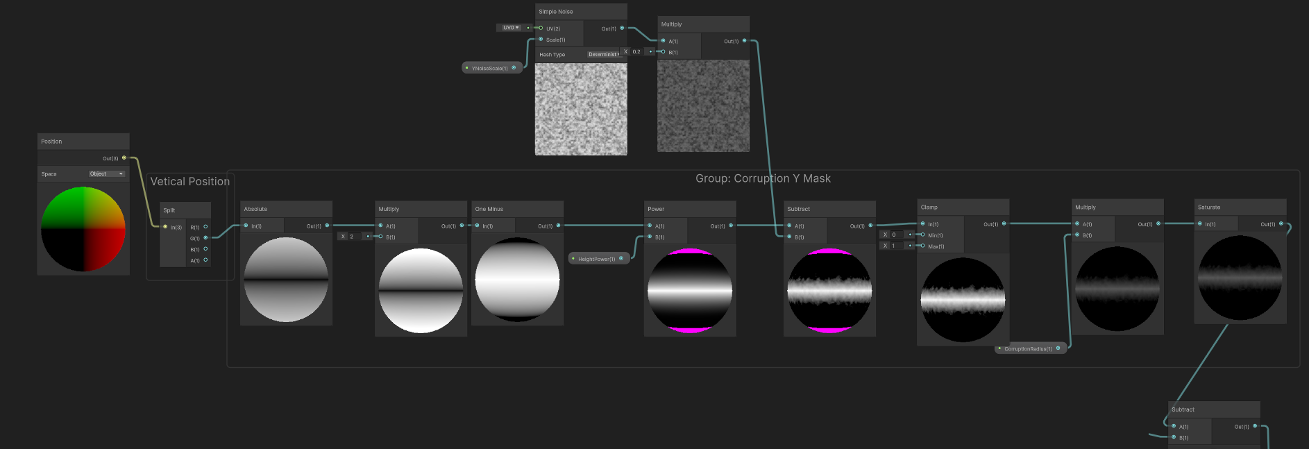
Simple Noise nodes. By independently adjusting the XZ and Y scales, we artificially create a directional bias—elongated in the downwind direction and compressed on the flanks.Subtract node to subtract 0.5 from the 0~1 noise. This shifts pure positive numbers into a range containing negatives, ensuring the flames oscillate back and forth across the original boundary, preventing the entire ring from migrating unidirectionally.Dimension 2: Height Clamping (Y Mask) Specifically addresses the “tree-climbing” stretching artifact (Pain Point 3).
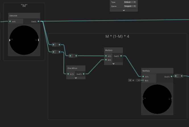
Position (World) node. This is fed into a Remap node to define the falloff zone, then a Power node controls the harshness of the fade, and finally, a Clamp restricts it between 0 and 1.M * (1-M) * 4 (Emission Edge Extraction & Final Blend)M.M * (1 - M), we extract a brilliant peak exclusively along the light-to-dark transition boundary. We take this razor-sharp flame ring, multiply it by our previously calculated Y Mask (to trim excess vertical climbing), and finally multiply it by our target color before feeding it into the Emission channel.Final Composite: Blending the mathematical edge extraction with the height mask
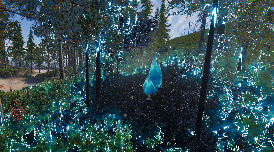
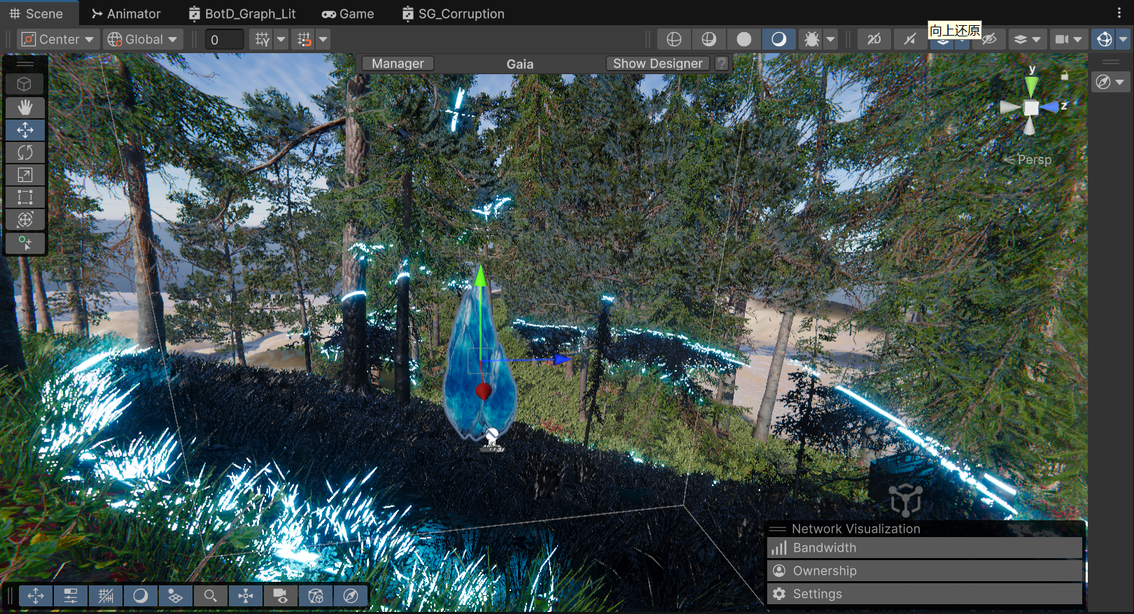
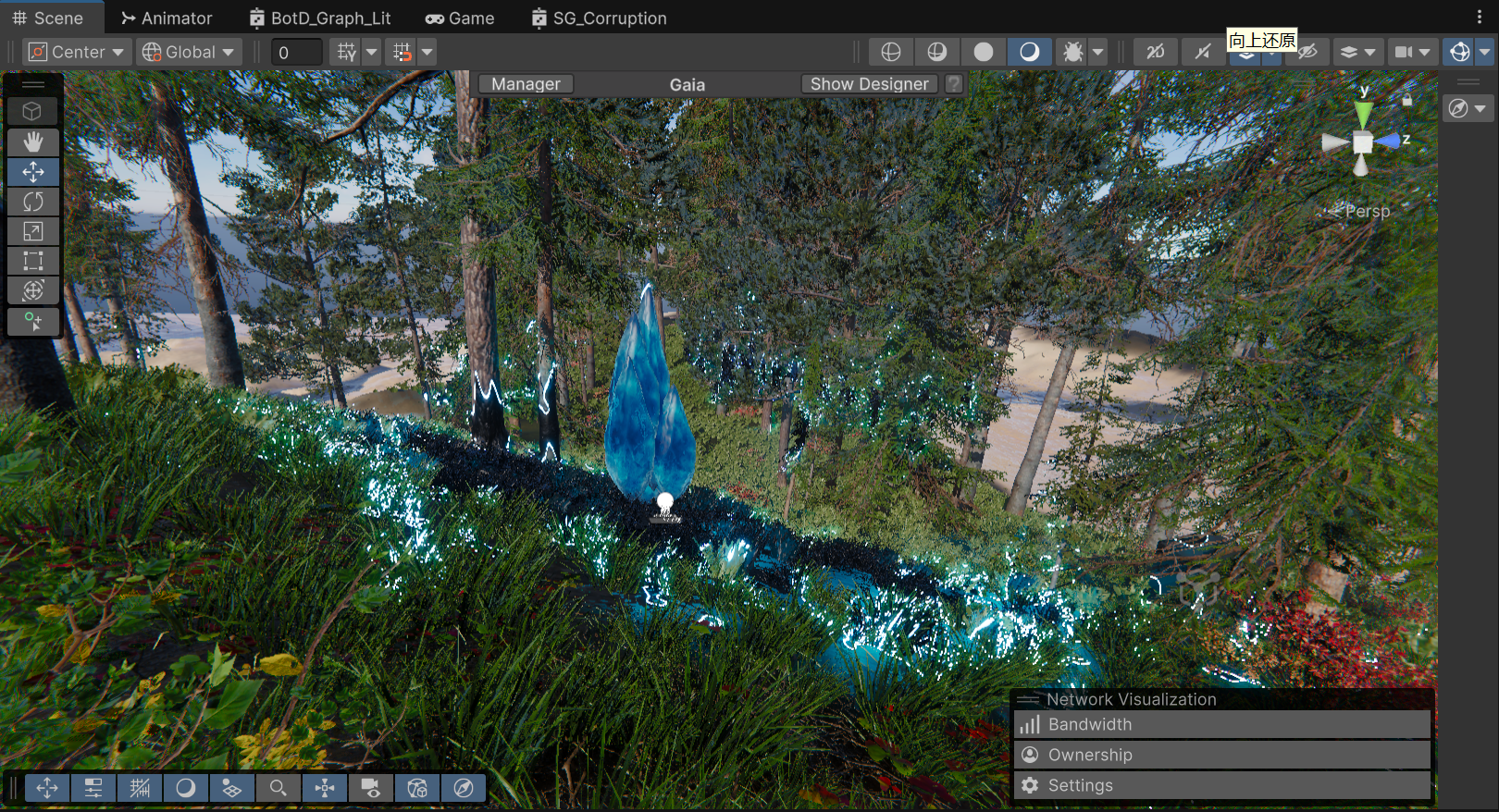
The Final In-Game Result
Currently, passing parameters via Shader.SetGlobalVector is incredibly performant and offers the best bang for our buck. However, keeping Enrico’s advice in mind, this setup can smoothly transition if environmental interaction demands increase.
Triggers for a Pipeline Upgrade:
When that day arrives, because our current Shader architecture already solidifies the underlying logic for “Static/Dynamic Decoupling” and “Planar/Height Separation”, we only need to swap out the few nodes receiving C# global variables. By replacing them with nodes that sample specific channels of a global Render Texture (e.g., reading the G channel for wind strength, B channel for footprint masks), we can seamlessly plug into a holistic environmental ecosystem like TVE.
Stepping back from a complex AAA architectural R&D phase to a streamlined mathematical implementation has been the most valuable lesson of this pipeline selection process. As Technical Artists, we must avoid the trap of treating everything like a nail just because we hold a powerful hammer.
By leveraging precise mathematical decoupling and height masking, we traded a handful of cheap ALU instructions for excellent volumetric visuals. More importantly, we clearly defined the boundaries of this solution while actively paving a smooth transition path toward a more robust RT architecture in the future.
Iteration Background & Positioning
While the pure math M * (1-M) * 4 approach was practically flawless in terms of performance, subsequent internal playtests revealed a visual shortcoming: the corruption felt too “passive” and “mild.” The Art Director’s vision demanded that the core area read as a highly unstable energy anomaly brimming with violent vitality.
It is crucial to clarify to the readers: This current iteration is strictly an “Art-Driven” visual proof-of-concept. Its primary mission is to achieve the highest Visual Target inside the engine without any compromises, establishing the benchmark for our art style. Once we hit this visual ceiling, we will inevitably subject it to rigorous performance downgrades and pipeline refactoring in the upcoming production cycles.
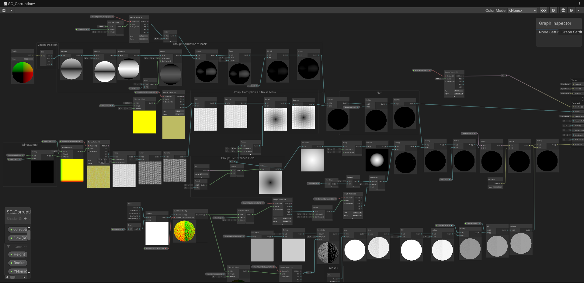
Technical Implementation Breakdown To achieve the “crackling wandering energy” and “rhythmic breathing pulse,” we completely refactored the core node group, introducing a highly expressive—albeit heavy—complex noise network:
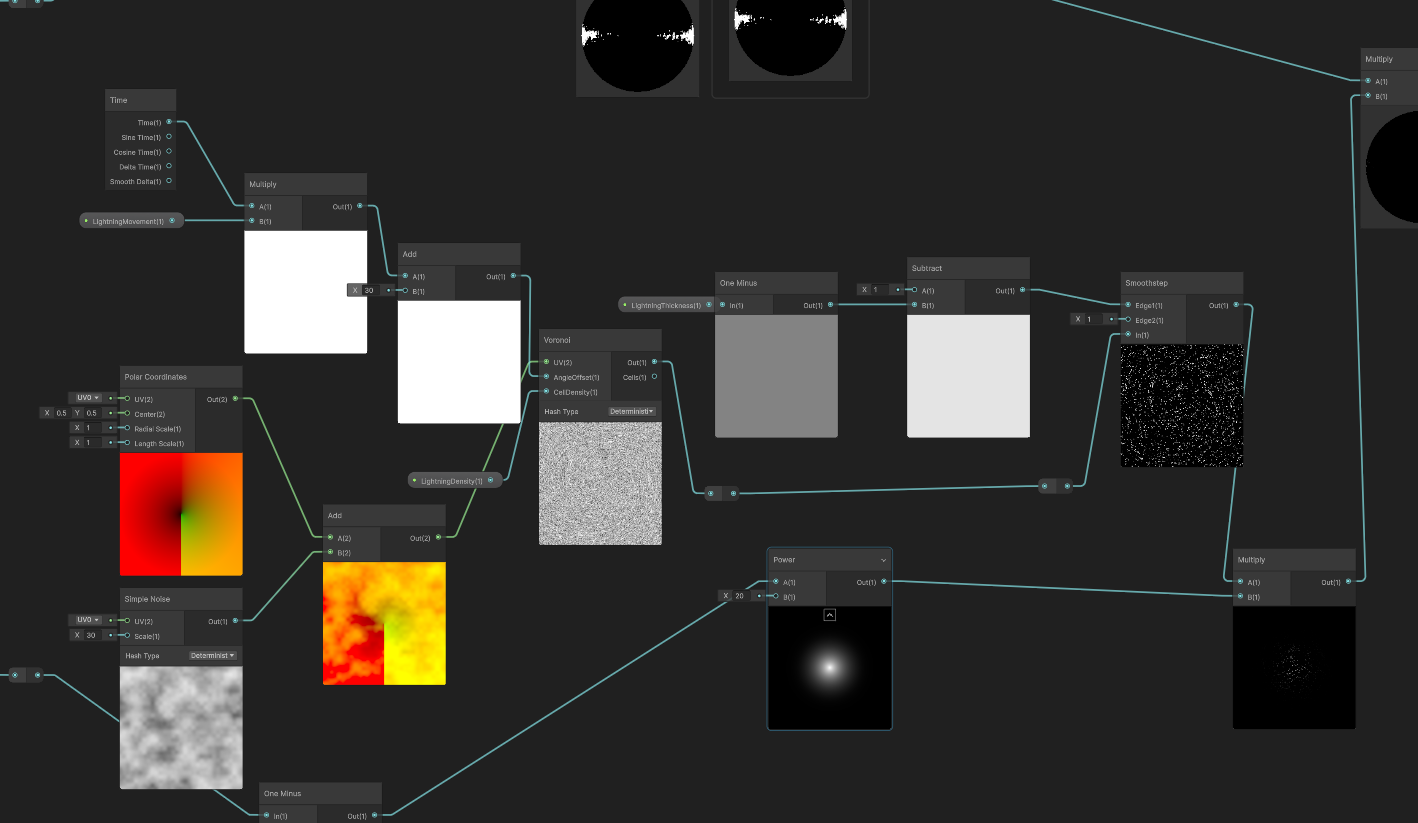
Core A: Polar Noise Composite Warping & Voronoi In-Place Evolution We abandoned simple UV panning, as it often just looks like a static texture sliding unnaturally across a surface. To imbue the energy with an outward-tearing and highly erratic sense of violence, we heavily customized the Voronoi noise across both spatial and temporal dimensions.
Spatial Dimension (Composite UV Tearing): First, the base UV is routed through a Polar Coordinates node to establish a radial spatial foundation. Simultaneously, we sample a standalone Simple Noise. The critical step: we take the output value of this basic noise and Add it directly to the output UV of the Polar Coordinates. This intensely warped, radially-biased, and uneven composite UV is then fed into the Voronoi node. This ensures the generated cellular structure is inherently torn through spatial distortion from the very beginning.
Temporal Dimension (Angle Offset Drive): Instead of using time to pan the UVs—the traditional trap—we take the accumulated time variable (Time * Movement), driven by the _LightningMovement property, and plug it directly into the Voronoi node’s Angle Offset port. This forces the Voronoi cell feature points to rotate, deform, and cannibalize each other in place, spawning an incredibly vivid, “crackling” wandering lightning dynamic that completely shatters the stiffness of linear panning.
Bandpass Filtering Extraction: Finally, to refine the chunky cellular shapes into razor-sharp lightning, we introduced the concept of Bandpass Filtering. We feed the Voronoi output into a Smoothstep node, locking Edge 1 at 0.1, while Edge 2 is dynamically controlled by the _LightningThickness property. This operation surgically extracts the microscopic “black gaps” crawling between the cells, instantly converting them into sharp, high-frequency, anti-aliased lightning meshes.
Step A: Composite UV Warping + Angle Offset Temporal Evolution + Smoothstep Bandpass Filtering to extract lightning meshes
Isolated Core A Effect: Discarding conventional UV panning to reveal an outwardly tearing, wildly erratic wandering lightning mesh.
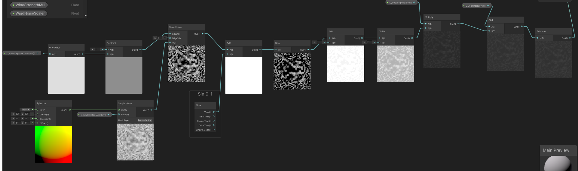
Core B: Spherize Cloud Base & Phase Shifting Pulse Beneath the wandering lightning meshes, we needed to lay down a “dark matter base” that could support the illusion of volume and throb like organic tissue. To create this slightly elevated, rhythmically pulsating physical illusion, we employed a highly elegant Phase Shifting technique:
Step 1: Constructing the Static Spherize Space & Cloud Base. We first pass the native UV into a Spherize node, sculpting a 3D convex-lens-like spatial base. This ballooned, distorted UV is then used to sample a Simple Noise (density governed by _L_BreathingNoiseScaler), generating a layer of static cloud cover with a volumetric, wrapping feel.
Step 2: Bandpass Texture Extraction (Smoothstep). The raw noise is too blurry and soft. We route it into a Smoothstep node, allowing the exposed _L_BreathingNoiseThickness property to dynamically hijack Edge 1 and Edge 2. Like a scalpel, this slices the blurry cloud into stark, high-contrast black-and-white static patches.
Step 3: Temporal Phase Drive & Sine Ripple. This is the core magic of the underlying logic. We do not move the UVs. Instead, using an Add node, we inject the continually accumulating Time variable directly into the grayscale values of the static patches we just extracted. This forces the numerical value of every single pixel to climb at a constant rate. We then feed this result into a Sine node. Because every pixel starts with a different initial grayscale value, processing them through a Sine function produces asynchronous, non-linear oscillation. Visually, this translates flawlessly into “breathing ripples” where the cloud base texture continuously expands and contracts in place.
Step 4: 0-1 Normalization. Given that a Sine wave outputs values oscillating between -1 and 1, overlaying this directly would cause color inversion or artifact blackouts. At the tail end of the logic chain, we use simple arithmetic—Add(1) followed by Divide(2)—to seamlessly remap the wave into an absolute positive range of 0 to 1, outputting a pristine breathing pulse mask.
Step B: Spherize Noise Extraction -> Temporal Value Addition -> Sine Phase Ripple -> 0 to 1 Normalization
Isolated Core B Effect: The Phase Shifting pulse in action, creating an organic, volumetric breathing ripple at the base.
Core C: Energy Aggregation & HDR Exposure Physical Enhancement
Finally, we multiply and merge the lightning texture (A) with the breathing noise (B), applying Saturate to strictly prevent negative value overflow. To ignite a genuine sense of energy within the HDRP environment, this dynamic mask is piped directly into an Exposure node before being multiplied by an extreme-intensity EmissionColor. This guarantees that even amidst drastic fluctuations in environmental lighting, the corruption core sustains a blindingly bright, physically accurate emissive Bloom.
Iteration Result: A highly oppressive visual performance merging ionization and breathing.
Ultimate Composition: The complete VFX suite integrating the procedural core with Render Textures, Post-FX Bloom, Refraction, and Volumetric Fog.
As emphasized earlier, this current version exists to secure “visual sign-off.” Calculating Voronoi, Polar Coordinates, and Spherize in real-time during the Fragment stage incurs a heavy ALU (Arithmetic Logic Unit) overhead that cannot be ignored. For an environmental decal that might be massively deployed across a scene, this level of consumption is unsustainable.
Future Optimization Strategy: Procedural to Texture Baking
Can we switch to using textures instead? Absolutely, and it is the mandatory path toward large-scale production. Once the visual target is unequivocally locked in, our next iteration will focus entirely on “baking” these expensive mathematical calculations into lightweight static assets:
UV Panning combined with Flow Map distortion will allow us to nearly perfectly simulate the current dynamic Voronoi calculations at a fraction of the cost, trading ALU overhead for cheap Texture Fetches.atan2) and spherize distortion math from the Shader. Instead, we will bake a UV Lookup Table (LUT) texture containing the polar distortion, or simply downgrade the effect to utilize a pre-rendered Flipbook sequence.Camera Distance. This will allow players to witness the high-fidelity procedural calculations within a 5-meter proximity, while smoothly Lerp-ing down to the cheapest static single texture for anything beyond 15 meters.Following the “Art-Driven” visual approval documented in Section 6, we immediately initiated the performance reclamation phase. The goal was simple: Ruthlessly eliminate all real-time procedural noises while preserving the chaotic, “breathing lightning” visual identity.
We executed a global purge across the Shader Graph. Every instance of Voronoi, Polar Coordinates, Spherize, and the 4 Simple Noise nodes was permanently deleted. Leaving these in the graph—even disconnected—is an industrial taboo, as they can cause variant bloat and confuse future maintainers.
In their place, we introduced a pre-baked Texture (T_Flow(RG)_Cell(B)_Noise(A)) authored in Substance Designer. This single texture packs our essential data:
Replacing Polar Coordinates with a Flowmap presented a new challenge: simple UV panning looks unnatural, and applying a modulo (Fraction) to the time variable causes a jarring, instantaneous visual reset when the value jumps from 1 back to 0. Similarly, using a PingPong (triangle wave) approach resulted in an awkward “breathing/accordion” artifact where the flow reverses direction.
The industrial-standard solution is Flowmap Blending (Dual Phase).
The custom Flowmap Blending Subgraph. Notice the strictly decoupled static directional vector and the time-driven dual phases.
To prevent infinite stretching, we resolve the “snap” of the cycle by running two identical engines ( and ) with a half-cycle offset:
Lerp node toggles between them, hiding the jump.TA Note: When sampling Flow vectors (RG), ensure the texture is not compressed using standard block compression (ASTC/BC7) and ideally exported at 16-bit precision to avoid “grid-like” vector quantization artifacts.
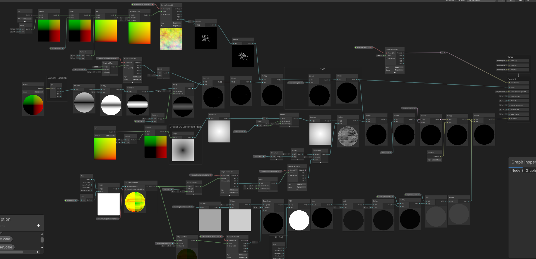
With the heavy lifting shifted to textures and Flowmap Blending, we restructured the Main Graph to cleanly separate the Micro Detail (texture sampling) from the Macro Masking (world-space constraints).
The finalized Main Graph: Procedural nodes purged, relying on texture caches and decoupled macro-masking logic.
A crucial mathematical fix was implemented for the central radial mask. Previously, relying solely on a raw Distance node left the edges of the 1x1 quad with a value of ~0.5, causing the lightning noise to bleed aggressively into the hard edges of the decal box.
By adjusting the math to Saturate(Distance * 2.0) -> One Minus, we forcibly pushed the 0.5 edge distance up to 1.0 before inversion. This acts as a surgical scalpel, guaranteeing a pure, pitch-black falloff at the perimeter, keeping the corruption perfectly contained within its radial bounds.
While the performance gains of this refactor are undeniable, it is vital to document a specific visual compromise we accepted during this transition: the slight loss of the erratic, “crackling” lightning behavior.
In our procedural iteration (Core A), we drove the Angle Offset of the Voronoi node using Time. Mathematically, this caused the cellular walls to dynamically collapse and reconnect, generating true Topological Evolution.
By switching to a pre-baked static Voronoi texture (T_Flow(RG)_Cell(B)_Noise(A)) distorted by a Flowmap, we are no longer evolving the cells. Instead, we are physically smearing a 2D image plane. Consequently, the lightning tendrils now inherently appear as continuous, warped lines (akin to stretched taffy) rather than disjointed, snapping arcs.
The finalized Main Graph: Procedural nodes purged, relying on texture caches and decoupled macro-masking logic.
Mitigation Strategies:
Angle Offset evolution into a low-cost 16-frame flipbook and playing it through the Flowmap pipeline would recover the chaotic cell-snapping dynamics at a fraction of the procedural ALU cost.Iteration Background: As we moved from the R&D sandbox into rigorous environmental placement, we hit a few unexpected integration hurdles.
Upon further stress-testing, I decided to completely refactor the underlying spatial masking logic. We stripped out the convoluted UV-based distance fields and unified all clipping strictly under Position (Object) space. By generating a pure 3D capsule intersection (), we restored absolute, mathematically perfect control to the Radius and Height parameters.
The refactored spatial masking pipeline. Notice the clean separation of Vertical and XZ constraints.
Subtracting by Addition (Removing the Wind): During this refactor, we made a crucial art-direction call: We completely removed the dynamic wind distortion from the decal. Why? Because our environment’s procedural grass shaders already react beautifully to the global wind parameters. Having the glowing ground decal also warp with the wind created visual clutter and redundancy. By letting the grass carry the “wind feedback” and keeping the energy decal focused on pure, crackling emission, the scene immediately felt more grounded and performed noticeably better.
Furthermore, this frees us up for our next major step: transitioning away from relying solely on a 2D Decal. By treating this shader as just the “base burn mark” and layering it with actual GPU particles and volumetric meshes, we can break the monotony of planar projections.
With the spatial masking stabilized in Unity, the focus shifted to the raw texture quality. The heavy “brush stroke” feel was a byproduct of pushing a standard Histogram Scan too hard on low-frequency noise, which inherently yields smooth, vector-like edges.
To achieve the aggressively sharp, crackling lightning threads (the “Tar vine” look), we had to abandon simple thresholding and develop a dedicated “Skeleton Extraction and Scatter” pipeline in Substance Designer.
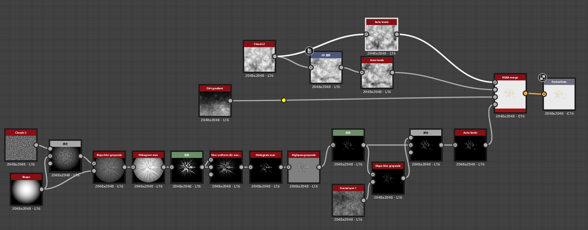
Substance Designer node cluster: Highpass Grayscale -> Levels -> Slope Blur -> Blend.
As illustrated in the node cluster above, the secret sauce lies in this specific four-step operation:
Highpass grayscale): We completely bypassed Histogram Scan. Instead, the torn radial shapes were fed into a Highpass filter. This acts as a non-linear frequency separator, discarding the bloated glowing areas and isolating only the most extreme structural transitions.Levels): Immediately following the Highpass, an aggressive Levels node crushes the remaining mid-tones to absolute black. What survives is a razor-sharp, sub-pixel-width energy skeleton.Slope blur grayscale + Fractal sum 1): A pristine, sharp line looks too “digital.” To break this, we split the output of the skeleton. One branch is fed into a Slope Blur driven by a high-frequency Fractal Sum noise. This operation physically chews up the smooth edges of the skeleton, introducing chaotic, organic electrical tearing and atmospheric dispersion.Blend): Finally, we use a Blend node (Screen/Lighten) to recombine the clean, sharp skeleton (representing the blinding energy core) with the slope-blurred, distorted version (representing the surrounding energy scatter).This dual-layer compositing strategy provides a solid, intensely bright structural core surrounded by erratic, crackling micro-details. When this meticulously crafted texture is multiplied by our refactored 3D Master Mask and pushed through HDRP’s EmissionColor, it completely sheds the flat “painted” look.
The result is a volatile, highly aggressive volumetric plasma base—perfectly optimized, visually fierce, and ready to be combined with our broader VFX toolset.
No video available.