Gallery
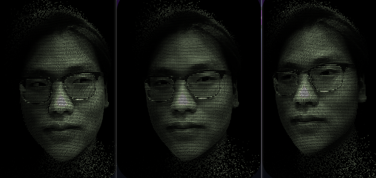

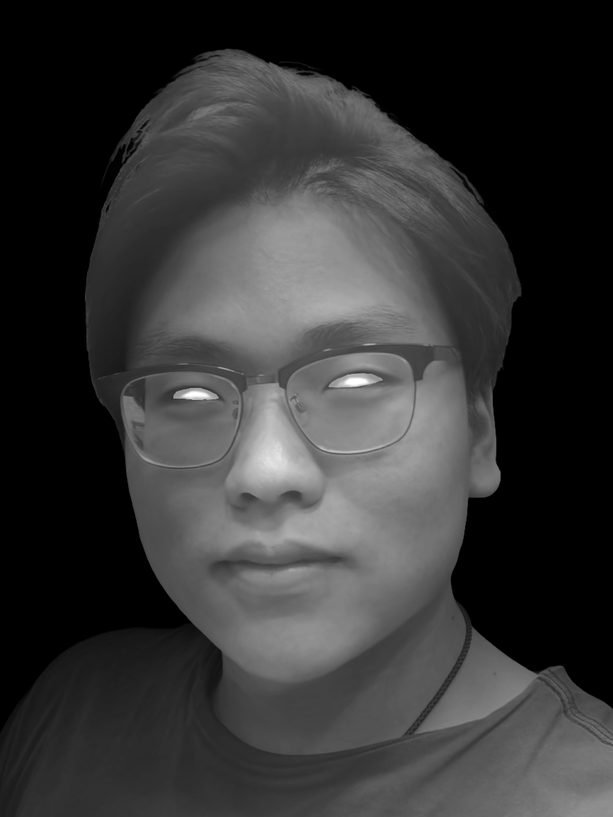
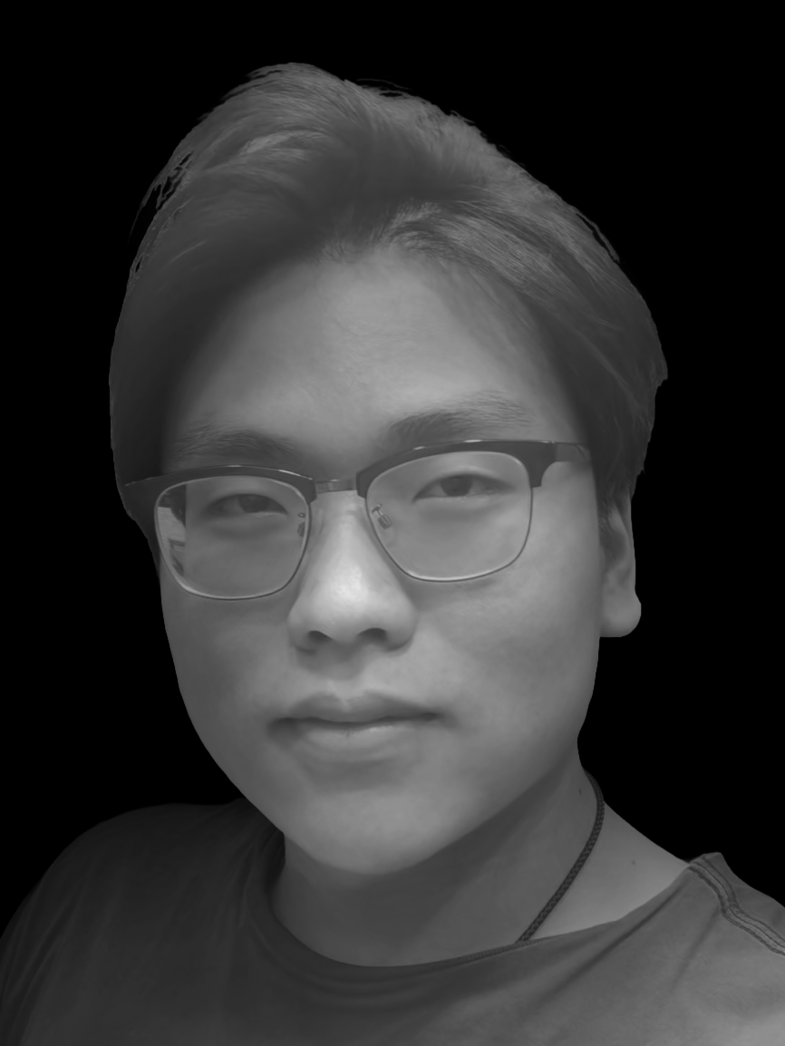
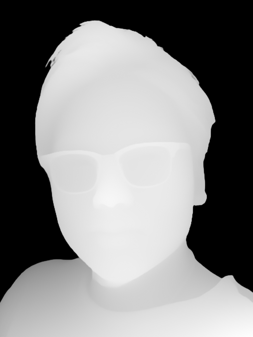
A study on converting a static 2D portrait into an interactive 3D particle cloud. It uses a Depth Map to drive vertex displacement and utilizes local coordinate transformations for eye tracking. The core challenges involved calibrating the rotation axis for strabismic eyes and implementing layer blending based on Alpha channels.
📄 Click to expand source code: ParticleFace.jsx
import React, { useRef, useMemo, useEffect } from 'react';
import { Canvas, useFrame, useThree } from '@react-three/fiber';
import { useTexture } from '@react-three/drei';
import { useControls, Leva, folder } from 'leva';
import * as THREE from 'three';

// ============================================================================
// 1. SHADERS (Graphics Logic Layer)
// Logic decoupled into helper functions for better readability
// ============================================================================

const vertexShader = `
  uniform float uTime;
  uniform sampler2D uDepthMap;
  uniform sampler2D uNoiseMap;
  uniform float uStrength;
  uniform float uNoiseAmp;
  uniform float uNoiseSpeed;
  uniform float uEdgeLow;
  uniform float uEdgeHigh;

  varying float vDistance;
  varying vec2 vUv;

  // --- Helpers ---

  // Calculate edge noise displacement
  vec3 getNoiseDisplacement(vec2 uv) {
    float distToCenter = distance(uv, vec2(0.5));
    float edgeMask = smoothstep(uEdgeLow, uEdgeHigh, distToCenter);

    vec2 noiseUV = uv + vec2(uTime * uNoiseSpeed, uTime * uNoiseSpeed * 0.1);
    vec4 noiseColor = texture2D(uNoiseMap, noiseUV);

    vec3 displacement = (noiseColor.rgb - 0.5) * uNoiseAmp;
    return displacement * edgeMask;
  }

  // --- Main ---
  void main() {
    vUv = uv;

    // 1. Depth check and culling
    float depth = texture2D(uDepthMap, uv).r;
    if (depth < 0.01) {
      gl_PointSize = 0.0;
      return;
    }

    // 2. Base position calculation
    vec3 pos = position;
    float sign = depth < 0.5 ? -1.0 : 1.0;
    pos.z += depth * uStrength * sign;

    // 3. Apply edge breakup and micro-movement
    vec3 noiseDisp = getNoiseDisplacement(uv);
    pos += noiseDisp;
    pos += noiseDisp * 0.005 / max(uNoiseAmp, 0.001); // Maintain subtle micro-movement

    // 4. Projection
    vec4 mvPosition = modelViewMatrix * vec4(pos, 1.0);

    float baseScale = 30.0;
    float perspective = 1.0 / -mvPosition.z;

    // 5. output
    gl_PointSize = baseScale * perspective;
    vDistance = -mvPosition.z;
    gl_Position = projectionMatrix * mvPosition;
    }
`;

const fragmentShader = `
  uniform sampler2D uFaceMap;
  uniform sampler2D uEyeMap;
  uniform float uContrast;
  uniform vec2 uEyeOffset;
  uniform float uEyeRotation;
  uniform vec2 uEyeCenter;
  uniform bool uDebug;

  varying float vDistance;
  varying vec2 vUv;

  // --- Math Helpers ---
  vec2 rotate2D(vec2 v, float a) {
    float s = sin(a);
    float c = cos(a);
    return vec2(v.x * c - v.y * s, v.x * s + v.y * c);
  }

  // --- Logic Helpers ---

  // Calculate Eye UV (includes physical movement logic)
  vec2 getEyeUV(vec2 uv) {
    vec2 centered = uv - uEyeCenter;
    vec2 rotated = rotate2D(centered, uEyeRotation);
    return rotated + uEyeCenter + uEyeOffset;
  }

  // Blend layers (Alpha Compositing)
  vec4 blendLayers(vec4 face, vec4 eye) {
    return mix(eye, face, face.a);
  }

  // Post-processing (Grayscale, Contrast, Fog)
  vec3 applyColorGrading(vec3 color, float dist) {
    // Grayscale
    float gray = dot(color, vec3(0.299, 0.587, 0.114));
    // Contrast
    gray = (gray - 0.5) * uContrast + 0.5;
    // Distance fog
    float fog = 1.0 - smoothstep(8.0, 17.0, dist);
    // Final brightness
    float brightness = gray * (fog + 0.4);
    // Green filter
    return vec3(brightness * brightness);
  }

  // Debug overlay
  vec4 applyDebug(vec4 originalCol, vec2 uv) {
    if (uDebug && distance(uv, uEyeCenter) < 0.01) {
      return vec4(1.0, 0.0, 0.0, 1.0);
    }
    return originalCol;
  }

  // --- Main ---
  void main() {
    // 0. Particle shape culling (Circle)
    if (distance(gl_PointCoord, vec2(0.5)) > 0.5) discard;

    // 1. Sampling and calculation
    vec4 faceCol = texture2D(uFaceMap, vUv);
    vec4 eyeCol  = texture2D(uEyeMap, getEyeUV(vUv));

    // 2. Blending
    vec4 finalCol = blendLayers(faceCol, eyeCol);

    // 3. Transparency culling
    if (finalCol.a < 0.1) discard;

    // 4. Debug mode check (Output directly if red dot)
    vec4 debugCol = applyDebug(finalCol, vUv);
    if (debugCol.r > 0.9 && debugCol.g < 0.1) {
       gl_FragColor = debugCol;
       return;
    }

    // 5. Final color grading output
    vec3 gradedColor = applyColorGrading(finalCol.rgb, vDistance);
    gl_FragColor = vec4(gradedColor, 1.0);
  }
`;

// ============================================================================
// 2. CUSTOM HOOKS (Logic Abstraction Layer)
// Separate config and loading logic from main component
// ============================================================================

function useFaceTextures() {
  const textures = useTexture([
    '/assets/Graphics/Shaders/face_depth/face_color_no_eyes.png',
    '/assets/Graphics/Shaders/face_depth/eyes_color_only.png',
    '/assets/Graphics/Shaders/face_depth/face_depth.png',
    '/assets/Graphics/Shaders/face_depth/noise_texture.png'
  ]);

  useEffect(() => {
    const [ , eyesMap, , noiseMap] = textures;
    // Set texture wrap modes (Side Effect)
    eyesMap.wrapS = eyesMap.wrapT = THREE.RepeatWrapping;
    noiseMap.wrapS = noiseMap.wrapT = THREE.RepeatWrapping;
    eyesMap.needsUpdate = true;
    noiseMap.needsUpdate = true;
  }, [textures]);

  return textures;
}

function useFaceControls() {
  return useControls('Face Settings', {
    Rendering: folder({
      strength: { value: 4.7, min: 0, max: 10, step: 0.1 },
      contrast: { value: 1.3, min: 0.5, max: 1.7, step: 0.1 },
    }),

    Noise: folder({
      noiseAmp: { value: 1.8, min: 0, max: 5, step: 0.1 },
      noiseSpeed: { value: 0.15, min: -1, max: 1, step: 0.01 },
      edgeLow: { value: 0.33, min: 0, max: 0.7, step: 0.01 },
      edgeHigh: { value: 0.53, min: 0.0, max: 0.8, step: 0.01 },
    }),

    // Physics parameters (using your latest tuned values)
    EyePhysics: folder({
      eyeRangeX: { value: 1.70, min: 0.0, max: 2.5, step: 0.01 },
      eyeRangeY: { value: 0.8, min: 0.0, max: 1.5, step: 0.01 },
      eyeRotation: { value: -1.23, min: -10, max: 10, step: 0.01 },
      trackingSpeed: { value: 1.5, min: 0.01, max: 1.5, step: 0.01 },
    }),

    // Calibration tools
    Calibration: folder({
      debugCenter: { value: false, label: 'show curr eye center' },
      centerX: { value: 0.43, min: 0, max: 1, step: 0.001 },
      centerY: { value: 0.53, min: 0, max: 1, step: 0.001 },
    }, { collapsed: true })
  });
}

// ============================================================================
// 3. SCENE COMPONENT (Composition Layer)
// Connects Hooks and Shaders, handles Frame Loop
// ============================================================================

function SceneContent() {
  const pointsRef = useRef();
  const { viewport } = useThree();
  const scale = Math.min(1, viewport.width / 8.0);

  // 1. Call custom hooks
  const [faceMap, eyesMap, depthMap, noiseMap] = useFaceTextures();
  const config = useFaceControls();

  // 2. Initialize Uniforms
  const uniforms = useMemo(() => ({
    uTime: { value: 0 },
    uFaceMap: { value: faceMap },
    uEyeMap: { value: eyesMap },
    uDepthMap: { value: depthMap },
    uNoiseMap: { value: noiseMap },
    uStrength: { value: 0 },
    uContrast: { value: 0 },
    uNoiseAmp: { value: 0 },
    uNoiseSpeed: { value: 0 },
    uEdgeLow: { value: 0 },
    uEdgeHigh: { value: 0 },
    uEyeOffset: { value: new THREE.Vector2(0, 0) },
    uEyeRotation: { value: 0 },
    uEyeCenter: { value: new THREE.Vector2(0.5, 0.5) },
    uDebug: { value: false }
  }), [faceMap, eyesMap, depthMap, noiseMap]);

  // 3. Frame Loop (Update Loop)
  useFrame((state) => {
    if (!pointsRef.current) return;
    const mat = pointsRef.current.material;
    const time = state.clock.elapsedTime;

    // Update base parameters
    mat.uniforms.uTime.value = time;
    mat.uniforms.uStrength.value = config.strength;
    mat.uniforms.uContrast.value = config.contrast;
    mat.uniforms.uNoiseAmp.value = config.noiseAmp;
    mat.uniforms.uNoiseSpeed.value = config.noiseSpeed;
    mat.uniforms.uEdgeLow.value = config.edgeLow;
    mat.uniforms.uEdgeHigh.value = config.edgeHigh;

    // Update calibration parameters
    mat.uniforms.uEyeCenter.value.set(config.centerX, config.centerY);
    mat.uniforms.uDebug.value = config.debugCenter;
    mat.uniforms.uEyeRotation.value = config.eyeRotation * (Math.PI / 180);

    // Calculate physics movement (Lerp interpolation)
    const targetX = (-state.pointer.x * config.eyeRangeX) / 100;
    const targetY = (-state.pointer.y * config.eyeRangeY) / 100;
    const currentX = mat.uniforms.uEyeOffset.value.x;
    const currentY = mat.uniforms.uEyeOffset.value.y;

    mat.uniforms.uEyeOffset.value.set(
      THREE.MathUtils.lerp(currentX, targetX, config.trackingSpeed),
      THREE.MathUtils.lerp(currentY, targetY, config.trackingSpeed)
    );

    // Head follow movement
    const headTargetY = state.pointer.x * 0.2;
    const headTargetX = -state.pointer.y * 0.2;
    pointsRef.current.rotation.y += 0.05 * (headTargetY - pointsRef.current.rotation.y);
    pointsRef.current.rotation.x += 0.05 * (headTargetX - pointsRef.current.rotation.x);
  });

  return (
    <points ref={pointsRef} scale={[scale, scale, scale]}>
      <planeGeometry args={[6, 8, 150, 150]} />
      <shaderMaterial
        vertexShader={vertexShader}
        fragmentShader={fragmentShader}
        uniforms={uniforms}
        transparent={true}
      />
    </points>
  );
}

// ============================================================================
// 4. MAIN EXPORT (Layout Layer)
// ============================================================================

export default function ParticleFace() {
  return (
    <div>
      <div
        style={{
          width: '100%',
          background: 'radial-gradient(ellipse farthest-corner at center, #0f151c 45%, var(--gray-999) 100%)',
          position: 'relative',
          aspectRatio: '3 / 4',
          borderRadius: '20rem',
          overflow: 'hidden'
        }}
      >
        {/* DPR Adaptation: [1, 2] balances clarity and performance */}
        <Canvas
          dpr={[2, 3]}
          camera={{ position: [0, 0, 10], fov: 45 }}
          gl={{ alpha: true }}
        >
          <React.Suspense fallback={null}>
            <SceneContent />
          </React.Suspense>
        </Canvas>
      </div>
      <Leva fill collapsed theme={{
    colors: {
      elevation1: 'var(--gray-999)',  // 🎨 面板背景色 (最重要)
      elevation2: 'var(--gray-999)',  // 输入框/控件背景
      elevation3: 'var(--gray-700)',  // 悬停/Hover 状态背景

      accent1: 'var(--accent-regular)',     // ✨ 强调色 (拖动条、复选框选中时的颜色)
      accent2: 'var(--accent-regular)',     // 次要强调色

      highlight1: 'var(--accent-regular)',  // 选中或聚焦时的高亮
      highlight2: 'var(--accent-regular)',

      text1: 'var(--gray-0)',   // 主文字颜色 (数值)
      text2: 'var(--gray-100)',     // 次要文字颜色 (标签 Label)
      text3: 'var(--gray-200)',      // 更淡的文字 (注释等)
    },
    // 你甚至可以调圆角
    radii: {
      xs: '2px',
      sm: '4px',
      lg: '8px',
    },
  }}/>
    </div>
  );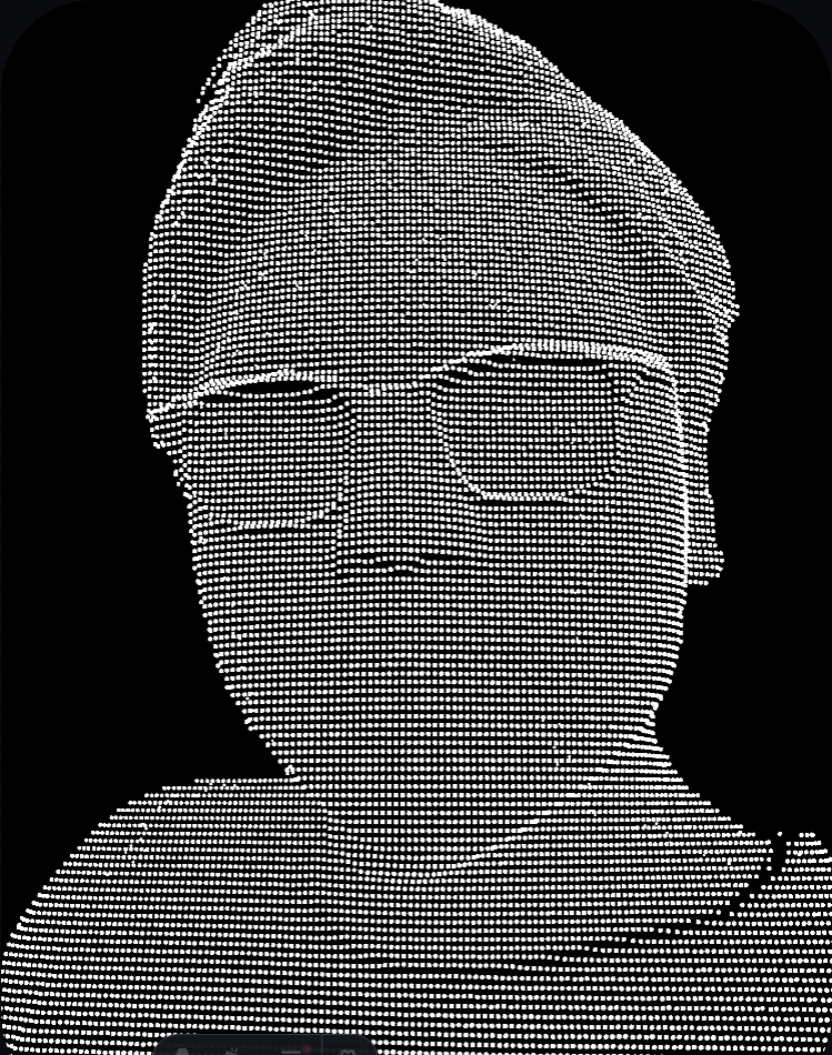
}Creating 3D face interactions usually requires complex scanned models or Blendshapes. My goal was radical simplification: To create a volumetric presence capable of tracking the mouse, using only a single 2D photo and Shader mathematics.
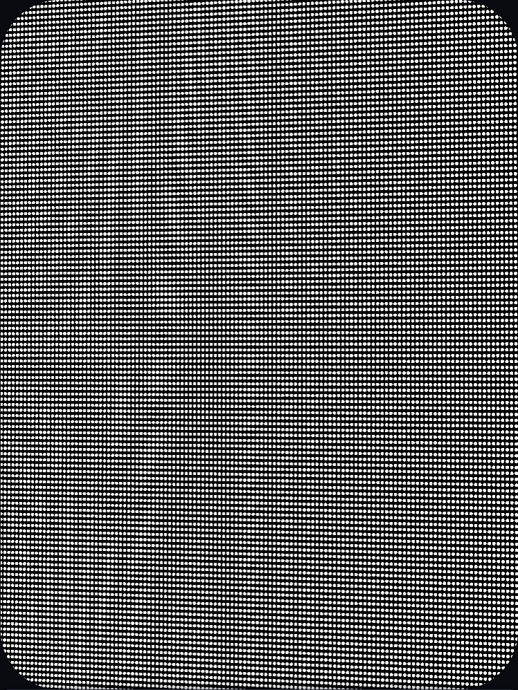
Instead of modeling, I chose to “cheat”. I used a high-density plane mesh (Plane Geometry, approx. 22,500 vertices), but the key lies in the rendering mode.
When rendering, I abandoned traditional triangle connections (Triangles) and rendered each vertex as an independent particle point (GL_POINTS).
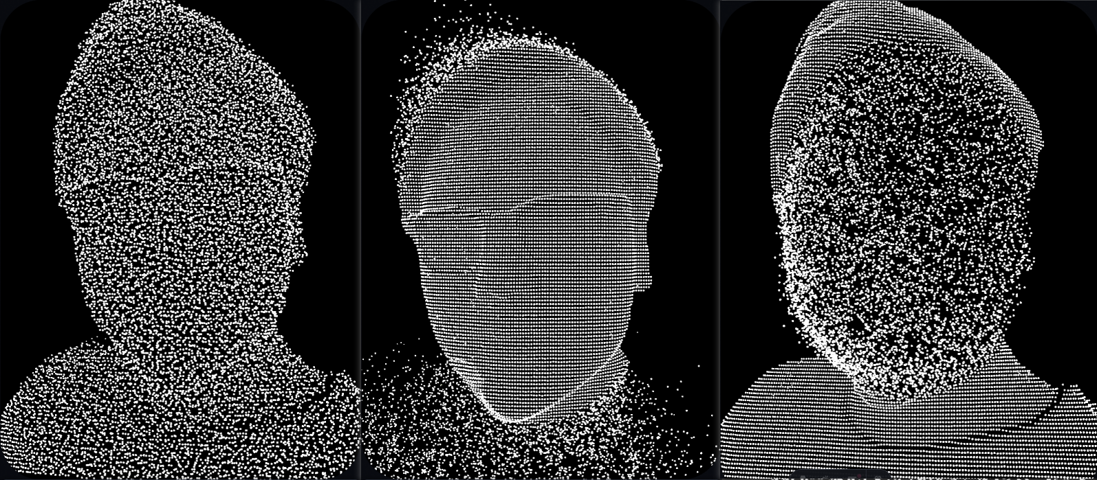
In the Vertex Shader, I first remove objects that should be considered background by reading the depth map values.
    if (depth < 0.01) {
      gl_PointSize = 0.0;
      return;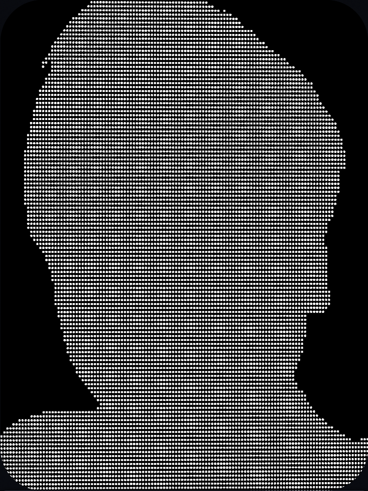
}Then, using the grayscale value from the depth map, I extrude the vertices along the Z-axis:
  vec3 pos = position;
  // 0.5 is the baseline: < 0.5 pushes back, > 0.5 pushes forward
  float sign = depth < 0.5 ? -1.0 : 1.0;
  pos.z += depth * uStrength * sign;
Note: The sign calculation ensures the model’s deformation remains centered around Z=0.0.
This transforms a flat plane into a 3D relief.
When calculating particle position and size, I utilize both View Space and Clip Space.
// 1. View Space
vec4 mvPosition = modelViewMatrix * vec4(pos, 1.0);

// 2. Particle Size Calculation (Size Attenuation)
gl_PointSize = baseScale * (1.0 / -mvPosition.z);

// 3. Clip Space
gl_Position = projectionMatrix * mvPosition;Why not just use the Projection Matrix directly?
mvPosition (View Space):
-mvPosition.z) to calculate physically correct “perspective scaling” (objects look smaller when further away). Using the Projection Matrix here would make the Z-axis non-linear, causing unnatural particle sizing.gl_Position (Clip Space):
Summary: We use the “Human Eye View” (View Space) to measure and size the particles, and then use the “Camera Lens” (Clip Space) to snap the photo for the screen.
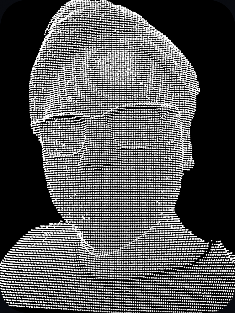
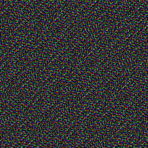
To disguise the fact that this is essentially a “deformed plane,” I implemented two key enhancements:
Pure Z-axis displacement makes the sides of the face look like stretched pasta.
uEdgeLow to uEdgeHigh).
vec3 getNoiseDisplacement(vec2 uv) {
    float distToCenter = distance(uv, vec2(0.5));
    float edgeMask = smoothstep(uEdgeLow, uEdgeHigh, distToCenter);

    vec2 noiseUV = uv + vec2(uTime * uNoiseSpeed, uTime * uNoiseSpeed * 0.1);
    vec4 noiseColor = texture2D(uNoiseMap, noiseUV);

    vec3 displacement = (noiseColor.rgb - 0.5) * uNoiseAmp;
    return displacement * edgeMask;
}

// In Main Function:
vec3 noiseDisp = getNoiseDisplacement(uv);
pos += noiseDisp;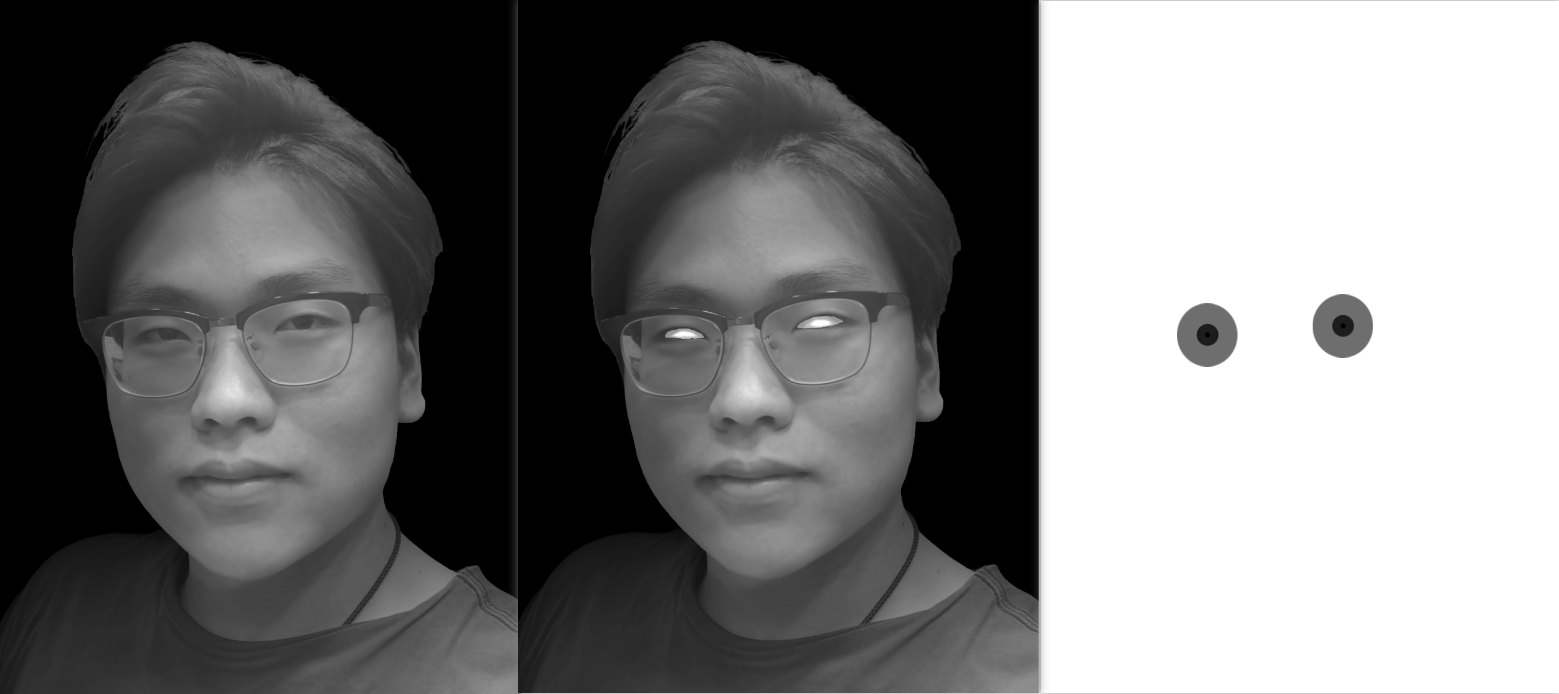
pos += noiseDisp * 0.005 / max(uNoiseAmp, 0.001); This is the most complex interaction. Without live eyes, the piece has no soul.
To make the interaction vivid, I designed two independent motion logic layers running simultaneously: one for the Eyes (Detail) and one for the Head (Global).
Moving the eyes isn’t just about shifting the image; it involves mathematical coordinate transformations.
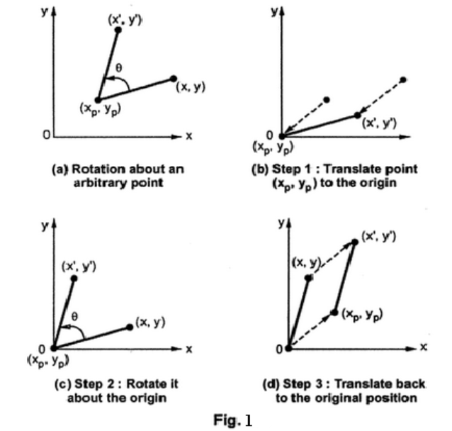
1. Local Coordinate System (Shader Calibration) Faces are tilted, and so are eyes. If we simply shift the UVs, the eyeballs will slide out of their sockets. We need to manually construct a “Virtual Eye Center” in the Shader.
uv - center).+ center).
// Fragment Shader
vec2 getEyeUV(vec2 uv) {
  vec2 centered = uv - uEyeCenter;
  // Key: Rotate the coordinate system first, then apply offset along the new axes
  vec2 rotated = rotate2D(centered, uEyeRotation);
  return rotated + uEyeCenter + uEyeOffset;
}
2. Physics Interpolation (JS Smoothing)
The uEyeOffset in the Shader doesn’t directly equal the mouse position, or the movement would look robotic. In the JS layer (useFrame), I used Lerp (Linear Interpolation) to add “weight” to the tracking:
// React Component (JS)
// Move current position only a small step towards target each frame
mat.uniforms.uEyeOffset.value.set(
  THREE.MathUtils.lerp(currentX, targetX, config.trackingSpeed),
  THREE.MathUtils.lerp(currentY, targetY, config.trackingSpeed)
);To enhance the 3D depth, the entire head rotates slightly with the mouse. This isn’t a Shader effect, but a rotation of the 3D Mesh itself.
// Simple Damping: current += (target - current) * 0.05
pointsRef.current.rotation.y += 0.05 * (headTargetY - pointsRef.current.rotation.y);
pointsRef.current.rotation.x += 0.05 * (headTargetX - pointsRef.current.rotation.x);Result: The eyes “chase” the mouse nimbly, while the head “turns towards” the mouse slowly. This Parallax (speed difference) greatly enhances the sense of volume and realism.
Initially, I used step(0.6, alpha) to distinguish between the face and the eyes.
I mimicked Photoshop’s layer blending logic.
The Trick: When Alpha is 0.4 (semi-transparent shadow), we see 40% Face Shadow + 60% Eyeball. This instantly gives the eyes a sense of volume, making them feel “sunken” into the sockets.
Although written in React, the graphics logic is universal. I’ve compiled this Concept Mapping Table for Unity developers.
There is a strict correspondence between React Three Fiber (R3F) functional components and Unity Object-Oriented Scripts (C#):
| R3F (React) | Unity (C# / MonoBehaviour) | Role & Explanation |
|---|---|---|
function SceneContent() { ... } | class SceneContent : MonoBehaviour | Defines a Component/Script Class. |
const pointsRef = useRef() | private MeshRenderer _points; | Member Variable. Persists references across frames, preventing garbage collection after function execution. |
useMemo(() => init(), []) | void Start() { init(); } | Initialization. Runs only once when the component mounts. Used for creating materials/data to avoid per-frame GC. |
useFrame((state) => loop()) | void Update() { loop(); } | Frame Loop. Logic executed every frame, such as Lerp interpolation and updating Shader params. |
React (WebGL):
The code uses the <points> tag directly, which maps to gl.drawArrays(gl.POINTS) in WebGL.
Unity Implementation: Unity’s standard pipelines (Standard/URP) default to Triangles.
mesh.SetIndices(..., MeshTopology.Points, ...).texture.wrapS = THREE.RepeatWrapping; // Manual settingMy GLSL code is split into helper functions for readability. In Unity Shader Graph, you can use Sub-Graphs to keep the main graph clean:
GetNoiseDisplacement: Create a Sub-Graph encapsulating noise sampling and edge masking logic.GetEyeUV: Create a Sub-Graph encapsulating the rotation matrix and UV offset logic.