Gallery
No video available.
Documenting the R&D process of the "Crystal Spatial Distortion" visual cue. We break down how to utilize the HDRP Custom Post Process Volume combined with Voronoi cellular noise to achieve a screen-space refractive fracturing effect that dynamically evolves with player distance.
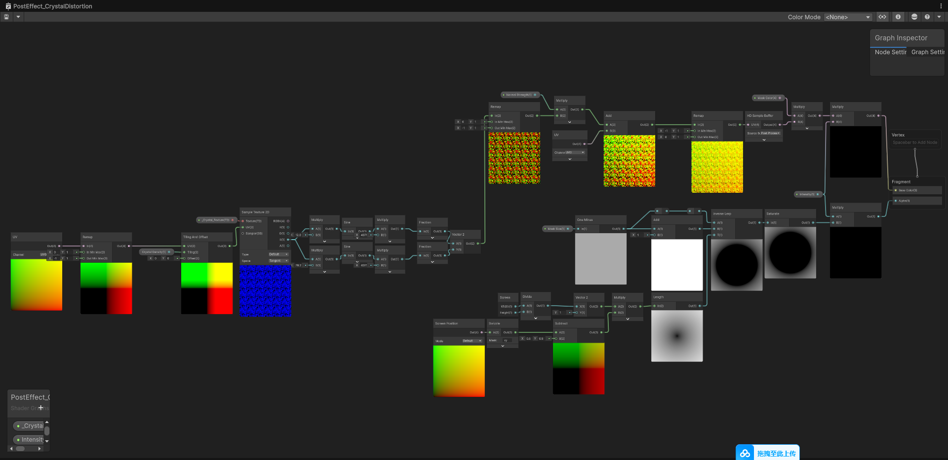
Although we are working within the HDRP Custom Pass interface, the shader effectively drives a full-screen rasterization process. Since we must calculate Voronoi IDs based on spatial coordinates and perform UV offsets at the pixel level, the computational heavy-lifting resides entirely within the Fragment Shader stage.
How do we accurately convey to players that they are stepping into a highly unstable anomaly where the spatial structure has crystallized?
To address this, the game design team proposed a clear visual cue: “Crystal Spatial Distortion.” The core challenge of this design lies in its dynamic scale evolution. When the player is at the edge of the anomaly (far away), the space should present a subtle refraction, as if filled with fine, shattered crystal dust. However, as the player pushes deeper into the epicenter, these fine particles must seamlessly grow into massive, fractured spatial crystal blocks that slice the physical environment behind them into jagged fragments.
This post-mortem will meticulously break down how we elegantly achieved this dynamic refraction effect relying entirely on Post-Processing, without adding any heavyweight AAA geometric overhead.
Before wiring up the node network, we had to determine the logical placement for this effect within the HDRP rendering pipeline.
Initially, we considered placing a colossal transparent refractive sphere (Transparent Mesh) at the center of the crystal anomaly. However, this approach presented fatal engineering flaws: the moment the camera clips through the sphere, the refraction logic instantly collapses. Furthermore, the Transparent Queue frequently triggers notorious depth-sorting disasters.
After careful evaluation, we locked in the HDRP Custom Post Process Volume approach.
Engineering Ingenuity: “Zero-Cost” Leveraging of HDRP Volume Blending
To achieve the “dynamic change based on distance to the center” requirement, the conventional method is to calculate Vector3.Distance every frame in a C# script’s Update loop and pass it to the Shader. We opted for a smarter route.
In our custom script PostEffectScript_CrystalDistortion.cs, we merely declared ClampedFloatParameter variables like intensity and CrystalDensity.
We directly utilized Unity’s native Local Volume Falloff mechanism. When a player steps into a crystal Volume configured with a Falloff distance, the underlying engine automatically and smoothly interpolates these exposed parameters. This completely eliminates the performance overhead of calculating distances in the logic frame, while also granting Level Designers immense freedom for parameter tweaking.
To recreate the sharp, aggressive texture of “shattered glass” or “crystal shards,” traditional Perlin noise was immediately discarded due to its overly smooth nature. We needed sharp polygonal boundaries, making Voronoi Noise the undisputed visual core of this phase.
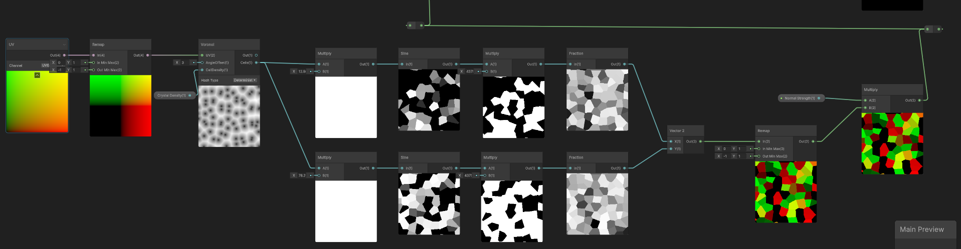
Here is the breakdown of the underlying node logic:
The visual evolution of the effect—from “fine crystal dust” to “shattered boulders”—is entirely dictated by the Voronoi’s Cell Density property.
_Crystal_Density parameter in real-time from the HDRP Volume system.💡 TA Tip & Workflow Note
When using Volumes to drive dynamic changes, there is a crucial engineering detail that must be synced with the Art and LD teams: Before the player enters the anomaly, what should the default “initial crystal particle size” be?
In our custom C# script, the parameter is declared as follows:
public ClampedFloatParameter CrystalDensity = new ClampedFloatParameter(25f, 0f, 50f);
The 25f here acts as the engine’s underlying Fallback Default when the player is not within the influence of any Local Volume.
For the sake of pipeline streamlining and peak performance, we strongly advise against placing a permanent Global Volume in the scene just to manage this initial state (which adds unnecessary post-processing overhead). Therefore, if artists later feel the “out-of-bounds fine particle size is off,” the most direct and performant solution is: Open the C# script and modify the default value in the parameter declaration. This is a zero-performance-loss correction method.
This is the most critical engineering hurdle in the entire Shader, and a common pitfall for beginners. We need “flat crystal facets individually fracturing the screen,” absolutely not “screen distortion that looks like water ripples.”
Engineering Pitfall: Why Abandon “Grayscale to Normal”?
Anti-pattern: Calculating normals based on grayscale gradients resulted in catastrophic high-frequency flickering during movement.
During the initial validation phase, we intuitively plugged the Voronoi grayscale output into a Normal From Height node to generate refraction normals. While it gave a basic crystalline feel, it brought along a disastrous “crushed diamond” flickering (aliasing).
Tracing the root cause: Normal conversion heavily relies on the height difference between adjacent pixels (the partial derivatives ddx / ddy). At the boundaries of Voronoi cells, the height value experiences a cliff-like drop, forcing the engine to calculate an extreme normal vector approaching infinity. When these razor-sharp edges shift or scale in screen space, the violent sampling offsets plunge the entire screen into frantic high-frequency flickering.
The Ultimate Solution: High-Frequency Truncated Pseudo-Randomness Based on Cells ID (Constant Hashing)
To eradicate the edge-case collapse caused by derivatives at the root, we decisively abandoned continuous grayscale gradients and instead extracted the Cells port of the Voronoi node. The brilliance of this port lies in its behavior: it assigns a universally consistent and unique constant float (a dedicated Cell ID) to every polygonal lattice on the screen.
Once the ID is extracted, how do we transform it into chaotic refraction directional vectors? We hand-wrote a classic, highly efficient Hash (pseudo-random) mathematical formula inside the Shader:
f(ID) = frac(sin(ID * C1) * C2)
To intuitively reveal how this “mathematical magic” operates, let’s plug in typical Shader constants (C1 = 12.9898, C2 = 43758.5453) to track the data flow:
Scenario 1: When adjacent lattice IDs are distinctly discrete values
| Lattice ID (Input) | Multiply by Constant (ID * 12.9898) | Sine Value sin(x) | Multiply by Massive Amplitude (43758.5453) | Fraction frac (Final Random Result) |
|---|---|---|---|---|
| 1.000 | 12.9898 | 0.410889 | 17979.9216 | 0.9216 |
| 2.000 | 25.9796 | 0.749204 | 32784.0572 | 0.0572 |
| 3.000 | 38.9694 | 0.955186 | 41797.5582 | 0.5582 |
| Observation: The initially orderly IDs are transformed into chaotic decimals, perfectly endowing different lattices with entirely unrelated normal offsets. |
Scenario 2: When there is a microscopic floating-point drift in the input ID
| Lattice ID (Input) | Multiply by Constant (ID * 12.9898) | Sine Value sin(x) | Multiply by Massive Amplitude (43758.5453) | Fraction frac (Final Random Result) |
|---|---|---|---|---|
| 1.000 | 12.9898 | 0.410889 | 17979.9216 | 0.9216 |
| 1.001 | 13.0027 | 0.422697 | 18496.6055 | 0.6055 |
| 1.002 | 13.0157 | 0.434433 | 19010.1684 | 0.1684 |
| Observation (The Butterfly Effect): A mere 0.1% micro-deformation at the input yields very little change at the Sine stage. However! When multiplied by the massive amplitude (C2), that microscopic difference is instantly amplified over 40,000 times and completely restructured. |
Algorithm Deconstruction:
frac acts like a pair of scissors, cleanly snipping away all integer parts, leaving only the final fractional tick mark where it stopped.Conclusion: A Dual Victory for Performance and Visuals
When this random result is assembled into a Vector2 and used as a UV offset, magic happens.
Because the same polygonal lattice (Cell) shares a singular unique ID, this means every single pixel inside that lattice, when plugged into the formula, calculates an absolutely identical displacement vector. There are no more derivative cliffs here, nor any height discrepancies between adjacent pixels. The screen is disjointed in solid, puzzle-like chunks, perfectly simulating the refraction of flat, hard-surface crystal facets, and mathematically eradicating the pixel-edge aliasing disaster from the ground up.
Step B: Abandoning normal conversion and using the Cells ID with a Sine hash algorithm to ensure each crystal block receives a flat, flicker-free refraction offset.
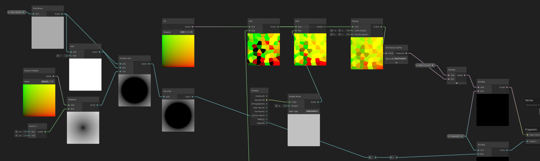
Screen Position, then use the HD Sample Buffer to grab the scene’s rendered color.Distance node, we measure the distance from the current screen UV to the exact screen center (0.5, 0.5). Combined with Inverse Lerp and a _Mask_Size property, we construct a precisely smoothed, decaying gradient ring.Step C: A smoothly decaying radial mask based on the distance to the screen center.
Final Effect: As distance decreases, spatial refraction smoothly transitions from microscopic crystal dust to giant fractured crystals.
Although the current version based on real-time Procedural Noise perfectly fulfills the artistic vision, it is unsustainable for mass production. Calculating a full-screen Voronoi distance field incurs a high ALU overhead. Especially in the “fine particle” state (high Density), the extremely dense sub-pixel calculations are frantically testing the hardware’s anti-aliasing limits.
Now that the visual effect is completely locked in, our next iteration goal is: “Baking” all these expensive mathematical operations into static assets.
Future Optimization Plan: Dimensional Baking & Texture3D Smooth Transitions
Many might question: If we just bake the noise into a standard 2D texture, wouldn’t simply “scaling the UV Tiling” as the player approaches completely lose the topological evolution of the Voronoi lattices “devouring and merging” into each other? Wouldn’t the dynamic vitality of the crystallization dry up?
This is exactly the core trump card of our performance optimization: Utilizing 3D textures and hardware-level interpolation for a dimensional strike.
Dimensional Escalation Baking (Texture3D Baking): We plan to generate a massive image sequence using external tools (or relying on engine built-in tools): evolving step-by-step from the highest density “fine gravel” to the lowest density “giant ice blocks.” We will stack these layers and pack them into a single Texture3D. In this three-dimensional texture, X and Y map to screen space, while the Z-axis perfectly substitutes for the crystal’s density (Density / Time) variation.
Hardware-Level Trilinear Filtering Magic:
In the production-ready Shader, we will ruthlessly strip out the Voronoi and Sine nodes, embracing a minimalist Sample Texture 3D. We will map the _Crystal_Density passed from the script to the Z-axis sampling depth of the 3D texture.
The most shocking magic lies here: When the sampling value falls between two density slices, the GPU will automatically activate hardware-native trilinear filtering, executing an ultra-smooth blend interpolation between the two texture layers. This perfectly recreates the physical illusion of seamless crystal growth in the player’s vision at an extremely low cost.
Pushing Performance to the Absolute Limit (O(1) Fetch): Coupled with a Flow Map that pre-stores the Vector2 displacements, we only need to pay the incredibly cheap price of a few Texture Fetches and minimal memory bandwidth to completely replace massive ALU computational power. There’s also a huge bonus: By utilizing the texture’s native Mipmap mechanism, we will eradicate the anti-aliasing flickering hazards of distant particles once and for all.
By elevating privileges to call the HDRP Custom Pass Volume and deeply exploiting the constant distribution characteristics of the Voronoi Cells port, we constructed a highly destructive spatial refraction experience using minimalist mathematical combinations. From the initial hard-coded mathematical validation to the future plan of utilizing Texture3D—a “trading space for time” philosophy that balances dynamic evolution with extreme performance—the evolutionary journey of this Shader vividly demonstrates the core value of a Technical Artist (TA) in bridging art and engineering.
The Context: In my initial implementation, I used the native Voronoi node in Shader Graph. While convenient, it is a notorious ALU hog.
AngleOffset animation, the performance gain on the frame debugger was a massive victory.The Hurdle: I spent a significant amount of time “talking to a brick wall” while debugging the shader. Even though my node setup looked perfect in the Shader Graph preview, the effect remained broken or jittery in the actual Game View.
My Finding: I discovered that in the HDRP Custom Post-Processing workflow, my C# Script (VolumeComponent) acts as the absolute dictator of material properties.
Render loop was firing m_Material.SetTexture("_Crystal_Texture", CrystalTexture.value) every frame. Since I hadn’t assigned the texture in the Volume Profile yet, the script was over-writing my graph’s defaults with null.To achieve the razor-sharp “Shattered Crystal” refraction I envisioned, I implemented a high-frequency Hash function:
f(ID) = frac(sin(ID * 12.9898) * 43758.5453)
My Technical Choice: I found that 8-bit or 16-bit (Half) textures were the root of my “Value Collapse.” When I multiplied a Cell ID by a constant as large as 43,758.5, the 16-bit mantissa simply didn’t have enough bits to hold the unique fractional data. This resulted in “Quantization Banding”—where multiple crystal facets incorrectly shared the same refraction vector, ruining the fractured aesthetic.
My Solution: The 32-bit (Full Float) Pipeline
To keep my Voronoi data mathematically “pure,” I’ve established a strict personal standard for importing these maps:
Point (no filter) — To stop bilinear interpolation from creating “ghost values” between cell boundaries.Disabled — To prevent the GPU from bleeding different Cell IDs together at a distance.Linear — To ensure my raw ID values aren’t warped by a Gamma curve.No video available.