Gallery
No video available.
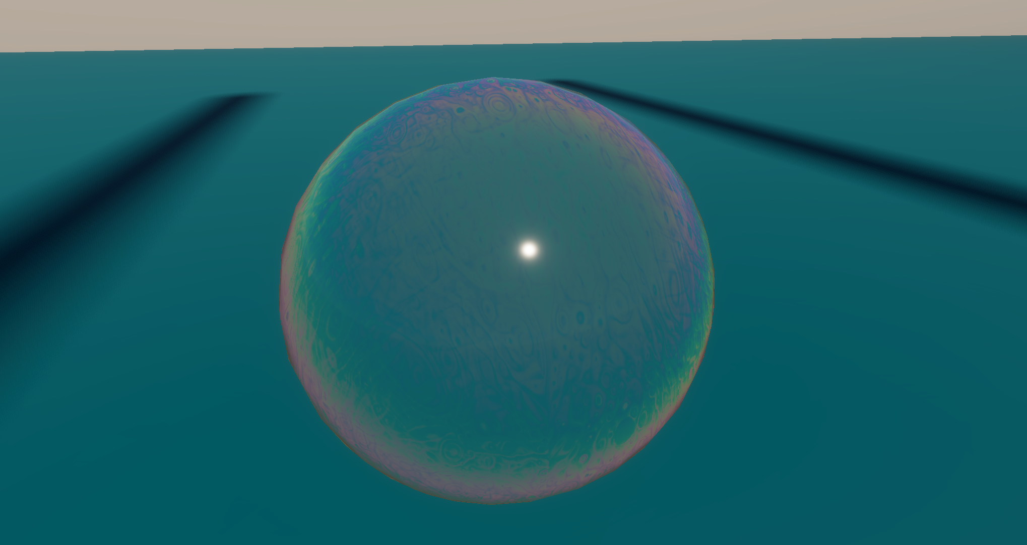

A real-time implementation of Thin-film Interference in Unreal Engine 5. This case study explores optimization via Look-Up Textures (LUT), solving UV topology artifacts with World-Aligned mapping, and non-standard PBR configurations.
This project focuses on replicating the physical phenomenon of Thin-film Interference in real-time. By deconstructing the interaction between light and microscopic surface layers, I translated complex optics into an optimized shader suitable for game engines. The goal was to achieve a fluid, realistic iridescent effect without the heavy cost of physical spectral integration.
The Physics: A bubble consists of an incredibly thin film of liquid with varying thickness. When light hits this surface, it undergoes complex reflection and interference at a microscopic level—similar to how a prism splits light. This constructive and destructive interference creates the shifting, rainbow-like colors we perceive at a macroscopic level.
The Optimization Strategy: Calculating actual spectral interference per pixel is computationally expensive. To optimize this, I used a Look-Up Texture (LUT) approach. This pre-bakes the complex physics into a texture gradient, allowing for lightweight sampling at runtime.
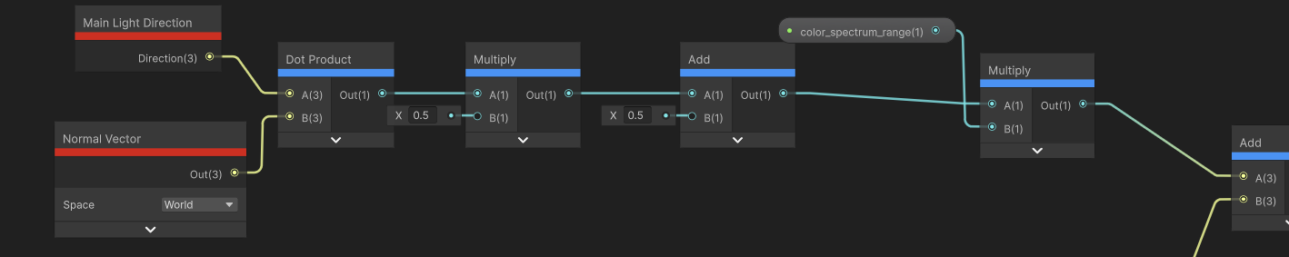
I simplified the physics into a straightforward “color lookup” operation based on the viewing angle:
Calculate Incidence: Compute the angle at which light hits the surface using the Dot product of the Surface Normal and View/Light direction ( or ).
Remap Coordinates: Convert the calculated cosine result into the range required for UV coordinates.
LUT Sampling: Use this coordinate to sample a pre-baked “Spectral Gradient Ramp.” The sampled color represents the interference result for that specific angle.
Result: Transforms a complex math problem into a simple texture lookup, significantly reducing GPU computational load.
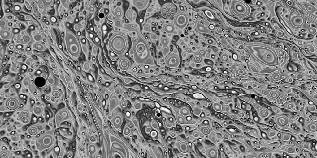
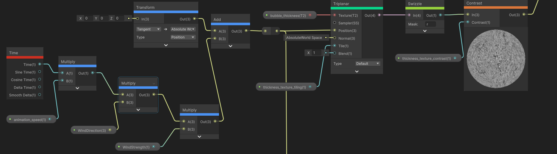
To simulate the fluid motion on the bubble’s surface, I processed a photo of a real bubble into a black-and-white noise texture. However, applying this to a sphere revealed a common problem:
The Artifact: Standard spherical UV mapping causes texture pinching (distortion) at the poles.
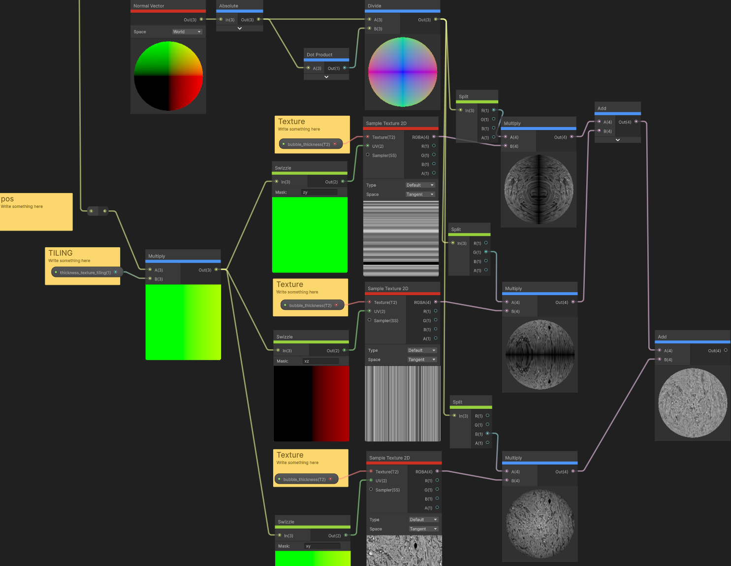
The Solution: I discarded the model’s default UVs and switched to Tri-planar (World-Space) Mapping.
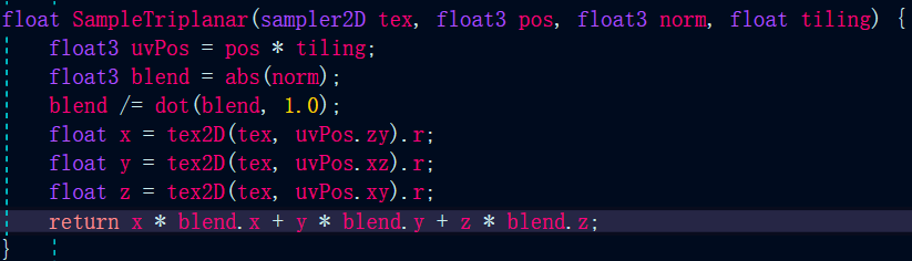
Implementation: Although Unreal provides built-in nodes, I implemented the logic from scratch to better understand the blending math. It projects the texture along the X, Y, and Z axes independently and blends them based on the absolute values of the vertex normal.
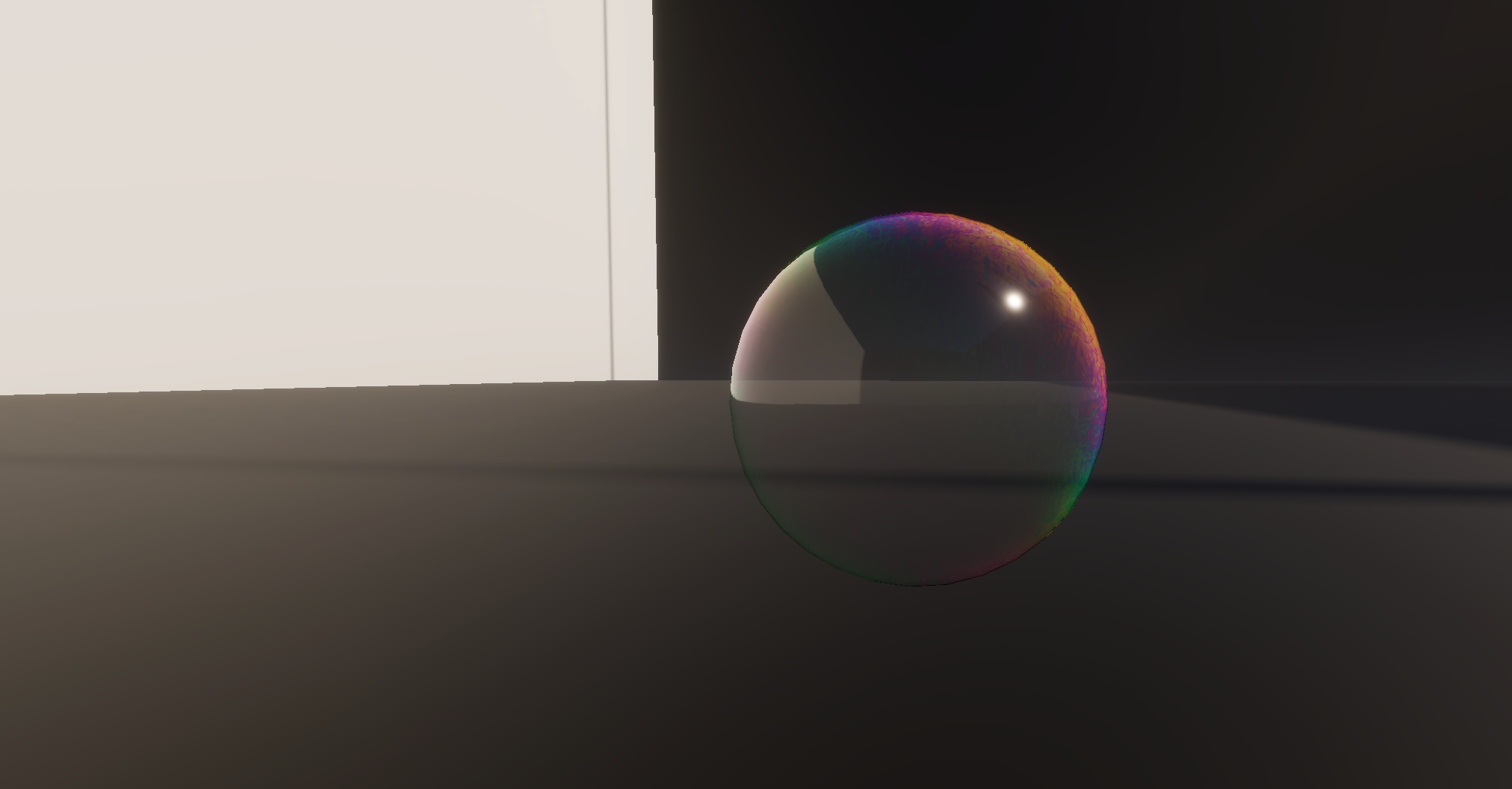
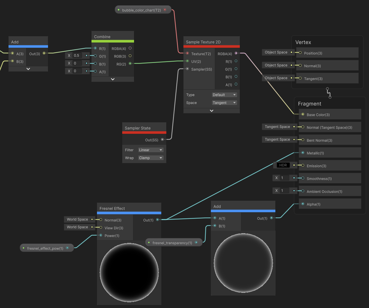
To achieve the specific aesthetic of a soap bubble, I used a somewhat counter-intuitive PBR configuration:
Metallic to 1.0.Base Color with Metalness at 1, the engine treats the rainbow as a pure reflection. This avoids the need for complex custom specular lighting models and results in a brighter, sharper look.
No video available.